CHAPTER 8 ACCELERATOR SHIELDING AND RADIOACTIVATION
Table of Contents
Article Page
PART 1 POLICIES AND PROCEDURES CONCERNING SHIELDING OF ACCELERATORS/BEAMLINES
812 Responsibilities for Configuration Control of Radiation Shielding
2. Prompt Radiation Shielding-Hadrons
3. Prompt Radiation Shielding-Muons
PART 1 POLICIES AND PROCEDURES CONCERNING SHIELDING OF ACCELERATORS/BEAMLINES
811 Policy on Design Criteria
1. Radiological control performance is affected by human performance and engineered design features. This Manual primarily addresses the way people operate and use existing facilities and sites. In addition, the following radiological control design criteria are provided for new facilities and major modifications to existing facilities:
a. Dose rates in areas of continuous occupancy shall be less than an average of 0.05 mrem/hr and as far below this as is reasonably achievable (see Articles 234 and 236). Dose rates for potential exposure to radiological workers in areas without continuous occupancy shall be ALARA and such that individuals do not receive more than 20% of the applicable limits as stated in Table 2-1.
b. Discharges of radioactive liquid to the environment are covered by the provisions of DOE 5400.5 (Chapter 2 Section 1, and Chapter 3) and the concentrations should be kept as far below the groundwater discharge limit as possible.
c. Contamination should be controlled by providing containment of radioactive material that has the potential for generating removable contamination.
d. Efficiency of maintenance, decontamination, operations, and decommissioning should be maximized.
e. Materials and components should be selected to minimize the radiological concerns.
f. Provisions should be made for donning and removal of protective clothing and for personnel monitoring, when appropriate.
g. Criteria for the conduct and review of shielding assessments are set forth in this chapter.
h. Internal exposure should be avoided by the use of engineered controls such as ventilation, containment, and filtration systems, where practicable (see also Article 316).
i. Dose to members of the public from all DOE airborne emissions sources should be maintained as low as reasonably achievable (see also Chapter 11).
2. Facilities currently under construction should be evaluated and the above criteria applied where practicable.
3. Locating eating areas, office space, rest rooms, drinking fountains, showers and similar facilities and devices within radiological areas is strongly discouraged. Unless office space is essential to support radiological work, steps should be taken to preclude unnecessary occupancy.
4. The design of facilities where neutron radiation is anticipated should use a quality factor of 10 unless measurements or calculations can demonstrate that a different quality factor more adequately describes the radiation field as given in 10 CFR 835.2 and reproduced verbatim in Tables 8-1 and 8-2. [To be updatd by July 8, 2010.]
5. New or modified accelerator/beamline facilities should have a shielding assessment performed, as specified in Article 812. (Many reference documents have been generated over the years at Fermilab and elsewhere that describe accelerator shielding design and radioactivation. These may be incorporated by reference in the accelerator/beamline shielding assessments, and are subject to the review procedures described in Article 812.)
6. For purposes of this article, a modification to shielding which requires a shielding assessment under Article 812 is one that has the potential to permanently change the level of personnel protection provided by radiation shielding. Such modifications include those which result in a permanent change to the personnel access status of an area or those which result in modification of the “official” as‑built drawings maintained by the Facilities Engineering Services Section (FESS) (see Article 812).
7. Division/Section ES&H personnel should be intimately involved in the conceptual radiological design process, and the design must also be reviewed by the ES&H Section.
8. The appendices to this chapter give suggested guidance concerning the technical aspects of estimating radiation shielding.
812 Responsibilities for Configuration Control of Radiation Shielding [To be updated by July 8, 2010].
1. Division/Section Heads are responsible for accelerator/beamline operations and those of the associated experimental program. These responsibilities include the fulfillment of the program elements listed below. They shall:
a. Develop and maintain a comprehensive inventory of beamline shielding against ionizing radiation in the areas assigned to them by the Director, and assure that the shielding complies with provisions of this manual.
b. Conduct a shielding assessment when new experiments are installed or when new beamlines are commissioned. Such assessments shall also be conducted when beamline operating conditions change such that the official “as-built” drawings maintained by the Facilities Engineering Services Section (see below) must be changed, or if the operating conditions (available intensity, energy, or particle type, etc.) result in a change to the access conditions applicable to a given area.
(1) The shielding assessment shall be a written description that includes calculations and measurements of possible radiation exposures, radiation shielding, beam optics and other relevant information. It shall address soil and groundwater contamination, airborne radionuclide releases and any associated required monitoring activities.
(2) The shielding assessment must document the circumstances and controls that serve to limit the intensity of the maximum beam loss and/or its duration.
(3) The assessment shall establish the occupancy status and radiological posting requirements of areas with respect to the posting criteria of Articles 234 and 236.
(4) The assessment shall be reviewed internally within the originating division/section (and within any other affected division/section) and approved in writing by the responsible division/section head(s).
(5) Modifications to shielding shall be reviewed by the Facilities Engineering Services Section for structural engineering impact. Changes to the original set of “as-built” drawings shall be coordinated with FESS.
(6) The assessment shall be submitted to the Senior Radiation Safety Officer for review in a timely manner prior to the conduct of the operations covered in the assessment.
(7) The shielding assessment documentation shall be maintained as “controlled documents” with copies filed in both the division/section office and in the ES&H Section Office.
c. Maintain shielding of beamlines in their area of responsibility and determine and document appropriate beam operating parameter limits required to meet ES&H requirements of this manual (the “safety envelope”).
d. Coordinate these responsibilities in regions of interface between divisions and sections.
e. Control the placement of temporary shielding in accelerator/beamline enclosures by some or all of the following provisions:
(1) appropriate labeling of such shielding to prevent its inadvertent removal
(2) appropriate securing of such shielding to prevent its inadvertent removal
(3) appropriate procedures for evaluating its effectiveness, and
(4) appropriate documentation, which becomes part of the permanent record of the operation.
f. Implement procedures to assure proper review and control of temporary modifications to permanent shielding that do not meet the criteria of 1.b.
2. The Senior Radiation Safety Officer shall:
a. Review the shielding assessment and, if appropriate, recommend written approval by the Director.
b. Maintain records of such reviews including file copies of the “as-built” shielding documents and the shielding assessment documentation and review protocols.
3. The Head of the FESS shall prepare and maintain the original set of “as-built” drawings documenting the status of radiation shielding. These drawings shall be approved by the appropriate division/section, the Senior Radiation Safety Officer, and the Director by signature. Thereafter Facilities Engineering Services will maintain the up-to-date originals of these drawings (and retain archival drawings of past conditions) while the ES&H Section and the appropriate division/section will be supplied up-to-date copies of the current shielding conditions.
Table 8-1 Quality Factors [To be updated by July 8, 2010].
The quality factors specified in 10 CFR 835 to be used for determining dose equivalent in rem without supplementary information about the details of the radiation field is shown below:
|
Radiation Type
|
Quality Factor |
|
X-rays, gamma rays, positrons, electrons (including H-3) beta particles) |
1 |
|
Neutrons < 10 keV |
3 |
|
Neutrons > 10 keV |
10 |
|
Protons and singly-charged particles of unknown energy with rest mass greater than one atomic mass unit |
10 |
|
Alpha particles and multiple-charged particles (and particles of unknown charge) of unknown energy |
20 |
If the spectral data are insufficient to identify the energy of the neutrons, a quality factor of 10 shall be used. Should one be able to determine the energy of the neutrons more exactly, the following quality factors may be used in determining the dose equivalent.
Table 8-2 Neutron Quality Factors [To be updated by July 8, 2010].
Mean quality factors, Q (maximum value in a 30-cm dosimetry phantom), and values of neutron flux density that deliver in 40 hours a maximum dose equivalent of 100 mrem (0.001 sievert). These values are specified in 10 CFR 835. For neutrons of higher energy, the value of Q is essentially independent of energy.
|
Neutron Kinetic Energy (MeV) |
Mean QF |
Neutron Flux (cm-2s-1) |
Neutron Energy (MeV) |
Mean QF |
Neutron Flux (cm-2s-1) |
|
2.5 x 10⁻⁸ (thermal) |
2 |
680 |
5 |
8 |
16 |
|
1 x 10⁻⁷ |
2 |
680 |
7 |
7 |
17 |
|
1 x 10⁻⁶ |
2 |
560 |
10 |
6.5 |
17 |
|
1 x 10⁻⁵ |
2 |
560 |
14 |
7.5 |
12 |
|
1 x 10⁻⁴ |
2 |
580 |
20 |
8 |
11 |
|
1 x 10⁻³ |
2 |
680 |
40 |
7 |
10 |
|
1 x 10⁻² |
2.5 |
700 |
60 |
5.5 |
11 |
|
1 x 10⁻¹ |
7.5 |
115 |
1 x 10² |
4 |
14 |
|
5 x 10⁻¹ |
11 |
27 |
2 x 10² |
3.5 |
13 |
|
1 |
11 |
19 |
3 x 10² |
3.5 |
11 |
|
2.5 |
9 |
20 |
4 x 10² |
3.5 |
10 |
813 Synopsis of General Methods Of Estimating Shielding and Radioactivation Applied to Accelerator Radiation Fields [To be updated by July 8, 2010].
1. Introduction
At high energy particle accelerators the design of adequate shielding becomes complex with increasing beam energy due to cascade phenomena. A high-energy hadron interacting with a nucleus typically creates a rather large number of short‑lived particles (pions, kaons, etc.), as well as protons, neutrons and nuclear fragments. Another important result of high-energy hadron interactions is the production of muons, which can represent a significant shielding problem. The interactions of the high energy beams can also produce significant radioactivation of the beamline components and the surrounding environment.
The purpose of this Article is only to provide a brief introduction to the topic of shielding and radioactivation and to collect some useful facts for “ready reference. It is not, by itself, a statement of Laboratory policies. In almost all circumstances it is far better to perform calculations specific to the details of the shielding configuration encountered than it is to excessively employ generalized calculations and “rules of thumb”. Thus, when practicable, modern shielding codes such as MARS should be used in accordance with FESHM Chapter 5201, "Usage of Computer Calculations Affecting Environment, Safety, and Health." Proper use of shielding computer models at the design stage can prevent design errors that are typically costly and difficult to correct.
The References section of this Appendix provides a list of useful sources of information that should be consulted. A detailed description of radiation physics at accelerators is found in Reference Fermilab TM-1834 (Co07), posted on the following website:
http://www-esh.fnal.gov/pls/default/esh_home_page.page?this_page=17080. This TM will be referenced elsewhere in this Chapter as “TM 1834”, often by individual chapter therein.
There are three principal reasons why accelerator and beamline components are shielded for radiation protection purposes:
a. to reduce the dose received by personnel during beam-on conditions;
b. to reduce exposure to personnel from highly radioactive targets and beam absorbers, etc.; and
c. to prevent contamination of the environment by creation of radioactivity in locations outside of areas controlled for personnel protection (see Chapter 11).
2. Prompt Radiation Shielding-Hadrons [To be updated by July 8, 2010].
a. Bulk Shielding
TM 1834 - Chapter 4 provides extensive information about the radiation fields due to protons and the application of shielding to mitigate them.
To correctly predict the behavior of the cascades in different materials arranged in an irregular geometry one must rely on computer programs that, to varying degrees, simulate these processes numerically (Monte Carlo method). A general description of the Monte Carlo method is provided in TM 1834 - Chapter 2. These codes use statistical techniques to "follow" through the shield the particles produced due to the incidence of primary protons. Various quantities are tabulated by location within the shield, generally by collecting them in geometrical bins specified by the program. The geometry of the shield is specifically incorporated into the calculation in accordance with the conventions of the program to the level of accuracy deemed appropriate by the user.
Historically, the code CASIM has been the main tool for doing such shielding calculations at Fermilab (Va75, Va87). Results obtained using this code still provide a benchmark for calculations of this type. The code MARS (Kr97) has supplanted CASIM as the code of choice for evaluating the shielding design of new projects and is now considered to be the general-use shielding code at Fermilab. This code is maintained by the Fermilab Physics Center.
Collections of "standard", idealized calculations using such codes have been produced (Va75, Sc90, Va87, Co82a) which can be helpful in evaluating commonly occurring situations. Further, the codes have been compared with each other, with results obtained with other codes used worldwide, and with experimental results (Aw75, Aw76, Co82a, Co82b, Co85, Mo86, Eb88, Su98, Sc90). Excellent agreement for well-understood conditions is the general result.
The primary output of calculations of this type is “star” (i.e., nuclear interaction) densities (stars cm-3 per incident proton) above a specified threshold momentum as a function of location in the thick shield. In the past, a threshold momentum of 300 MeV/c (47 MeV kinetic energy for nucleons) has customarily been used, but modern calculations with MARS allow for more flexibility so the value of this threshold must be clearly specified. Figures 8-1 and 8-2 are useful examples that show contours of star density in large solid iron and concrete shields for protons of 300 GeV/c incident momentum. Figure 8-3 is an idealization of a 300 GeV/c proton beam being lost on a magnet or collimator inside a tunnel. Figures 8-4 and 8-5 are similar to figures 8-1 and 8-2 except that they are for 1000 GeV/c incident protons.
The star density can be converted to dose equivalent and other quantities of radiobiological interest. The conversion factors relating star density to dose equivalent depends upon the momentum threshold assumed in the calculation, since particles below threshold can contribute to the dose, but not to the star density, and this contribution has to be included. There is a dependence of the conversion factors upon location in a shield. However, at sufficiently large depths or radii when the shape of the hadron spectrum approaches equilibrium they approach constant values.
Iron is sometimes used as part of hadron shielding at accelerators in order to minimize the space required for the shield by taking advantage of the higher density of iron relative to soil or concrete. To do this, one must be aware of a special physical effect, the so-called “iron leakage” problem that is extensively discussed in TM 1834 - Chapter 6 and which has been verified experimentally (El86). Calculations have indicated that an outer layer of 60-90 cm of concrete will compensate for this effect and allows one to utilize the higher density of iron shields to optimize the space required for shielding (Yu83).
Table 8-3 gives quantities of interest for four spectra: a “thin” iron shield (r » 20 cm) (Go76a) in which the high-energy particles still play a significant role; a “thick” iron shield (r » 100 cm) in which the spectrum is totally dominated by intermediate energy neutrons (El86), and the more familiar spectra found outside soil and concrete shields (El86). The results are a composite of those obtained using several different references cited. They include the contribution of the components of the neutron energy spectra that are below the "traditional" Monte Carlo threshold of approximately 300 MeV/c. These quantities should be calculated directly for individual shielding/beam configurations wherever it is practical to do so. Other results of measurements in accelerator neutron spectra at Fermilab are provided elsewhere (Co88, Co07 –Chapter 6).
Soil is generally considered to be equivalent to concrete in hadron shielding problems, provided one scales all dimensions to compensate for the lesser density of soil. One unit linear thickness (i.e., ft or cm) of soil is approximately equivalent (41.6/44.6) = 0.93 unit thickness of concrete where the multiplicative factor is the ratio of the high energy interaction lengths provided in Table 8-1. The density of compacted soil (i.e., heavy clay) is quite high at Fermilab (2.24 g cm-3) compared with the uncompacted value of about 2.0 g cm-3 (Mu83) and with values obtained at other facilities.
Table 8-3
Shielding and neutron spectral quantities of interest for four side-shield spectra produced by multi-hundred GeV protons. See original references for more details. Here t denotes the approximate thickness of the material. The "thin" iron is the layer struck by primary protons or first generation secondary hadrons. For general purposes, a "thick" shield can be considered to be one that is thicker than approximately 1 interaction length. The momentum threshold associated with the stars for proper use of this table is 300 MeV/c.
|
Spectrum |
Iron "Thin" t < 20 cm (Go76a) |
Iron "Thick" t » 100 cm (El86) |
Concrete "Thick" t » 100 cm (El86) |
Compacted Soil "Thick" (Inferred from El86) |
|
Density r (g cm-3) |
7.87 |
7.86 |
2.4 |
2.24 |
|
Absorption Length (cm) (gm cm-2) |
16.8 131.9 |
16.8 131.9 |
41.6 99.9 |
44.6 99.9 |
|
Average Quality Factor (Note 1) |
7.7 |
5.7 |
2.7 |
2.7 |
|
Absorbed Dose/Neutron Fluence (mrad/n-cm-2) |
2.4 x 10⁻⁶ |
1.7 x 10⁻⁶ |
5.7 x 10⁻⁷ |
5.7 x 10⁻⁷ |
|
Dose-Equivalent/Neutron Fluence (mrem/n-cm-2) |
1.9 C 10-5 |
9.5 x 10⁻⁶ |
1.6 x 10⁻⁶ |
1.6 x 10⁻⁶ |
|
Neutron Fluence/star-cm-3 (n-cm-2/Star-cm-3) |
526 |
44200 |
3060 |
3310 |
|
Absorbed Dose/star-cm-3 (mrad/star-cm-3) (Note 2) |
1.3 x 10⁻³ |
7.4 x 10⁻² |
1.8 x 10⁻³ |
2.0 x 10⁻³ |
|
Dose Equivalent/star-cm-3 |
1.0 x 10⁻² |
0.42 |
4.9 x 10‑3
|
5.3 x 10⁻³
|
Notes:
1. These are values from a well-measured or well-calculated spectra. See other references for alternative examples of spectra. For example, quality factors from (Co88) for "thick iron" spectra range from 5.7 to 6.9 and for "concrete" from 2.5-5.8. Thus, one reasonably takes the value of QF » 5 for "typical" neutron spectra when spectrum measurements are not available.
2. The values for concrete are adapted from (St86).
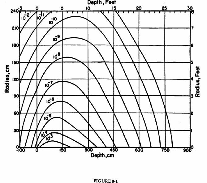
300 GeV/c protons incident on a solid iron cylinder. Contours of star density (stars cm-3 per incident proton) based on a CASIM simulation. The beam of 0.3 x 0.3 cm cross section is centered on the cylinder axis and starts to interact at zero depth. The star density includes only those due to hadrons above 0.3 GeV/c momentum. Contours of higher star density are not shown for clarity of the plot; those of lower star density are not included due to statistical uncertainty. (Fig. VIII.3 of Va75)
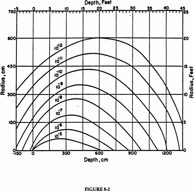
300 GeV/c protons incident on a solid concrete cylinder. Contours of star density (stars cm-3 per incident proton) based on a CASIM simulation. The beam of 0.3 x 0.3 cm cross section is centered on the cylinder axis and starts to interact at zero depth. The star density includes only those due to hadrons above 0.3 GeV/c momentum. Contours of higher star density are not shown for clarity of the plot; those of lower star density are not included due to statistical uncertainty. (Fig. VIII.20 of Va75)
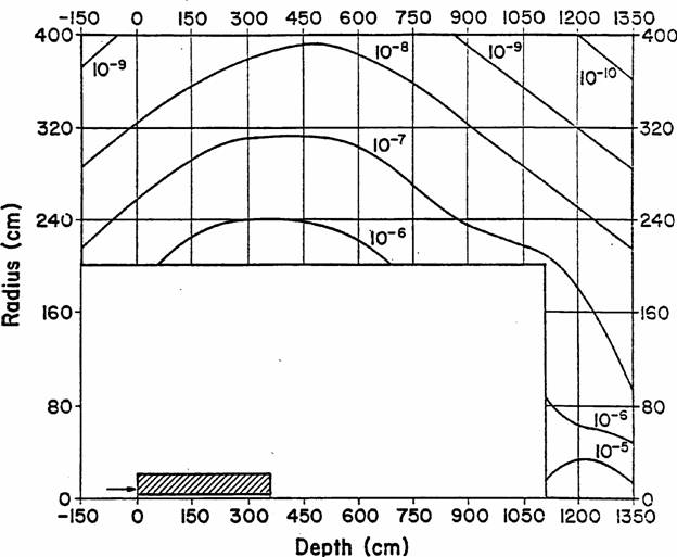
FIGURE 8-3
300 GeV protons incident on a steel “collimator” (or magnet) placed in a concrete enclosure based on a CASIM simulation. Contours of star density (stars cm-3 per incident proton) produced by hadrons above 0.3 GeV/c momentum. The collimator is a cylindrical shell, 360 cm long, with an outer radius of 20 cm and an inner radius of 3.75 cm. The beam has a square cross section of 0.1 x 0.1 cm and is centered at a radius of 4 cm. The contours show the star density averaged over azimuthal angle.
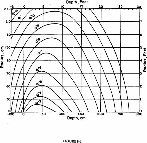
1000 GeV/c protons incident on a solid iron cylinder. Contours of star density (stars cm-3 perl incident proton) based on a CASIM simulation. The beam of 0.3 x 0.3 cm cross section is centered on the cylinder axis and starts to interact at zero depth. The star density includes only those due to hadrons above 0.3 GeV/c momentum. Contours of higher star density are not shown for clarity of the plot; those of lower star density are not included due to statistical uncertainty. (Fig. VIII.4 of Va75)
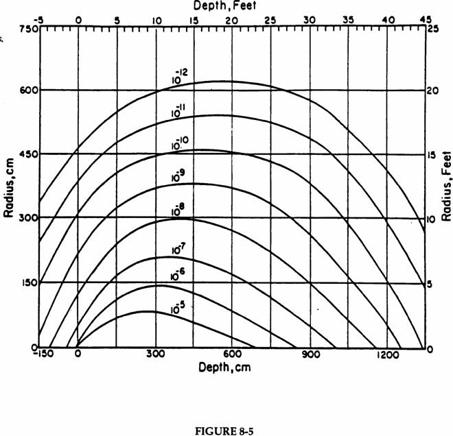
1000 GeV/c protons incident on a solid concrete cylinder. Contours of star density (stars cm-3 per incident proton) based on a CASIM simulation. The beam of 0.3 x 0.3 cm cross section is centered on the cylinder axis and starts to interact at zero depth. The star density includes only those due to hadrons above 0.3 GeV/c momentum. Contours of higher star density are not shown for clarity of the plot; those of lower star density are not included due to statistical uncertainty. (Fig. VIII.21 of Va75)
Figure 8-6
1000 GeV/c protons incident on a solid concrete cylinder. Fraction of the omnidirectional flux, entrance absorbed dose and maximum dose equivalent below hadron kinetic energy on abscissa (in MeV) for the region between zero and 450 cm depth and between 300 cm and 750 cm radius, based on a CASIM simulation. (Fig. VI.13 of Va75.)
b. Approximate Particle Flux to Dose Equivalent Conversion Factors
Hadrons, Muons, Electrons and Photons by Energy
Figures 8-7A and 8-7B show values of dose equivalent per fluence conversion coefficients for various particles). TM 1834 - Chapter 1, also provides values for neutrinos.
Figure 8-7A Dose equivalent per unit fluence conversion coefficients
[microSv/(particle cm-2)] as a function of energy adapted from (Sc90). One microSievert (mSv) = 0.1 mrem.
Figure 8-7B Dose equivalent per unit fluence conversion coefficients
[microSv/(particle cm-2)] as a function of energy adapted from (Sc90). One microSievert (mSv) = 0.1 mrem.
3. Prompt Radiation Shielding-Muons
Energetic muons are capable of traversing large distances through matter. Their long range (e.g., ~500 m of soil for a 300 GeV muon) strongly suggests that muon shielding be treated separately from hadron shielding. The problem of estimating muon dose rates can be conveniently divided into three parts: muon production, muon transport, and beam loss mode. The first two are encoded as part of the Monte Carlo codes such as MARS or CASIM (MUSIM for muons) that trace the development of hadronic and electromagnetic showers and include muons from all generations of the showers. In a typical application, beam loss mode and geometry is user supplied and encoded. This is entirely similar to the hadron shielding case. An empirical method, suitable for rough estimates, is given in TM 1834 - Chapter 4 and (Su92). As always, detailed calculations using the Monte Carlo programs are preferred for designs of large-scale shields against muons.
4. Labyrinth Design
The proper design of penetrations through shielding for both personnel and equipment is an important topic. It has been discussed in detail in TM 1834 - Chapter 5.
5. Skyshine Radiation
At most particle accelerators, the provision of roof shielding over large areas is problematic in that it represents a simultaneous optimization of the radiation shielding requirements and the civil engineering standards. The radiological aspects are discussed in detail in TM 1834 - Chapter 5.
6. Residual Radioactivity
a. Introduction
At all accelerators with energies greater than a few tens of MeV, induced radioactivity results whenever beams interact with accelerator or beam transport components, beam splitting stations, collimators, scrapers, target areas and beam absorbers. Some of these losses are deliberate and cannot be reduced. Those are usually the most radioactive areas of the accelerator, and work near them is the largest source of radiation exposure at all laboratories.
What follows is aimed primarily at practical applications at Fermilab; more general discussions may be found in (Ba69), (Go76), and (Co07). TM 1834 - Chapters 7 and 8 provide a more detailed discussion of the activation of accelerator components and environmental media, respectively.
b. General Considerations about Radioactivation at Proton Accelerators
The extranuclear hadron cascade process produces the major fraction of the induced radioactivity at proton accelerators. A high-energy particle, which interacts with a nucleus, may be absorbed and/or knock some nucleons out of the struck nucleus, with the latter process called “spallation”. Additional high-energy particles may also be created in the collision. If the resulting nucleus is highly excited, it will de-excite by “boiling off” so-called “evaporation neutrons.”
The resulting nucleus may be stable or radioactive. The cross section for producing a particular nuclide depends on the target nucleus and on the type and energy of the incident particle. These cross sections are best determined from experimental data. If such data is lacking, empirical formulae, such as that in (Ba69), give a good approximation to cross sections that vary over several orders of magnitude.
The particles in the cascade continue to propagate and decay or interact until their energy drops below the threshold for nuclear reactions; this is usually between 10 and 50 MeV. However, for some nuclides, neutron capture is an exothermic reaction with a large cross section for thermal neutrons. For example, the radioactivation of concrete occurs principally by thermal neutron capture of 23Na to produce 24Na with a 15-hour half-life.
c. Gollon Rules
These rules due to Gollon can be used for many “back of the envelope” calculations (Go76b). See TM 1834, Chapter 7 for a more complete discussion with numerical examples.
Rule 1: The exposure rate dD/dt (R/hr) at a distance r (meters) from a “point source” of gamma rays is given in terms of the source strength S (curies), the photon energy E (MeV), and the probability pi a particular photon is emitted when the nucleus decays, by:
![]()
where the summation is over all the photons emitted in the decay. The factor 0.4 is a combination of different constants and unit conversion constants.
Rule 2: In many common materials, about 50% of the nuclear interactions produce a radionuclide with a half-life longer than a few minutes. About half of these have half-lives greater than a day.
Using these rules, one can calculate the dose rate near a target a tenth of an interaction length long. (A much longer target would require a large correction for secondary interactions.)
Rule 3: For most common shielding materials, the exposure rate due to a constant irradiation is given by the following formula originally developed by Sullivan and Overton (Su65):
 .
.
Here f is the incident flux, B is a material and geometry-dependent constant, and ti and tc are the irradiation and cooling times, respectively. This is valid for those materials which yield many radionuclides upon irradiation and for tc > 12 min, (ti + tc) < 500 days. The constant B may be determined experimentally or by using Rule 2.
Rule 4: In a cascade, a proton typically produces about four stars for each GeV of kinetic energy.
d. Other Calculational Techniques
Advanced calculations require more information in the following areas:
Cascade Source Term: The spatial distribution and spectra of the particles in the hadron shower in the target of interest. The accuracy of the calculation will be enhanced in accordance with the degree of detail concerning target composition and geometry that is included.
Nuclear Reaction Data: Reaction cross sections for transforming various nuclei in the “target” into other, radioactive nuclei.
Radiological Data: Nuclear lifetimes, decay schemes, transport of b’s and g’s out of the activated object (i.e., self-shielding) and flux-to-dose conversion factors.
Monte Carlo codes such as MARS can now adequately handle the induced radioactivity problem (Su98, El02, Ra01).
A useful semi-empirical approach is due to Barbier (Ba69). Barbier separates the problem into two parts: the user is given the task of determining the flux of activating particles, while Barbier provided information on residual dose rate per unit activating flux. He derived his induced spallation cross sections from an empirical formula. Experimental values of nuclear lifetimes and decay characteristics were entered into these calculations. Transport of b and g-rays out of the material and conversion to dose rate was done in an appropriate analytic way. The results may be presented in terms of what Barbier called the “danger parameter.” This is the dose rate in a cavity inside an infinite volume of radioactive substance with uniformly distributed activity produced by unit hadron flux (1 particle cm-2sec-1). Curves of danger parameters for different materials are shown in Fig. 8-8 and are similar to conventional cooling curves. The danger parameter is a function of irradiation and cooling time, because isotopes with different lifetimes saturate and decay differently with time.
We can use one of these curves to determine the dose rate in real situations involving a thick source by using the following relation:
![]() .
.
The dose rate at any point, dD/dt, is obtained by multiplying the danger parameter (D) by the fractional solid angle (W/4p) the source subtends when seen from the point of interest and by the activating flux density (f) at the surface of the object. The activity several absorption lengths into the body does not contribute much to the external dose rate because of self-shielding of the gamma rays by the activated object. An alternate representation involves the hadron star density S (calculated by one of the standard Monte Carlo codes) in the activated material and a different parameter, w. The flux and star density are related: f = lS/r, where l is the interaction length expressed as mass per unit area (g cm-2), and r is the density of the material (g cm-3). Here, the quantities f and S include the beam intensity and are thus in units of particles cm-2 s-1 or stars cm-3s-1, respectively.
It is possible to obtain the hadron flux at the surface of the object from a Monte Carlo calculation run for that purpose, or from “standard” cases. If this is done, one must be careful because many Monte Carlo programs have a low-energy cutoff, below which they cease to follow particles. Since this cutoff may be higher than the thresholds of many activation reactions, use of the “flux” or “star density” predicted by the Monte Carlo calculation will give an erroneously low value for the activation. Correction for this effect may be made if the ratio of the true flux to the “Monte-Carlo flux” is known. This ratio is material dependent, and to the extent that the spectrum has not reached an equilibrium shape, it is position dependent as well.
For the 300 MeV/c (En = Ep = 47 MeV, Ep = 190 MeV) cutoff used by Van Ginneken, the proportionality constant for iron, w(ti, tc), is:
w(![]() ,0) = 9 C
10-6 rad hr-1/(star cm-3s-1), or
,0) = 9 C
10-6 rad hr-1/(star cm-3s-1), or
w(30d,1d) = 2.5 C 10-6 rad hr-1/(star cm-3 s-1).
e. An Additional Example
Figure 8-9 shows a calculation of Armstrong (Ar73) to which has been added the decay curves of a number of accelerator components made mostly of iron. The curve labeled “accel” is based on the measured cooling of the average dose rate around the Fermilab Main Ring. It had been operating for about 3 years with essentially constant losses; thus the curve ought to be comparable to the one labeled “one year”; but it falls about a factor of 3 below it for long cooling times.
The curve labeled “neutrino” represents the decay of an area near the target of the narrow band neutrino target train after a run of 8 months. The beam intensity varied by a factor of about two over this period. Again, the components cooled much faster than one would predict.
Finally, the curve marked “AGS” represents the dose rate near the Brookhaven AGS slow external beam splitter. This device had been operating for many years; its decay agrees reasonably well with the predictions for long irradiations, but still falls below the prediction.
As can be seen from the various graphs of the danger parameter, different materials vary widely in their relative hazards due to activation. Aluminum is preferred to iron because of its lesser activation - the only major long-lived activity produced from aluminum is 22Na. For shielding purposes, CaCO3, the principal constituent of marble, is excellent for the same reason; in this case the cross section for 22Na production from calcium is even lower. Elements above calcium, however, are capable of readily producing long-lived activity.
Sodium, on the other hand, is notorious for causing problems because of its high thermal neutron capture cross sections, producing 24Na. Concrete containing one percent of sodium by weight produces enough 24Na activity to approximately double the radiation level in the machine enclosure the first day after machine turn off. Since the major source of sodium in concrete is the aggregate, a proper choice of aggregate, such as limestone, can eliminate this problem. Evidence for the copious production of 56Mn (2.6 hrs half-life) by thermal neutron captures on traces of 55Mn in iron and concrete has also been observed. The neutron spectrum emanating from a thick 1 m radius iron shield was particularly rich in intermediate energy and thermal neutrons; additional thermalization occurred in the concrete. Traces of boron added to the concrete in the area would capture most of the neutrons and alleviate the problem.
f. Radioactivation of Soil and Air
The radioactivation of water, soil, and air is covered in detail in TM 1834 - Chapter 8. Within this Manual, see Chapters 3 and 11 for policies pertaining to such radioactivation.


